This is an old revision of the document!
Tapping mode measurements
Non-contact or intermittent contact measurements, known also as Tapping mode, are based on detection of change of probe resonance when it is affected by attractive and repulsive probe-sample interactions.
To set up the hardware for tapping mode measurements, the probe-sample force related signal, e.g. vertical deflection of the cantilever, has to be connected to input of lock-in 1. The excitation signal goes from fast output 1 and has to be connected to mechanical excitation of the probe cantilever, typically using a piezo amplifier and piezoelectric transducer on which the cantilever is mounted. The measurement mode has to be changed to “Tapping”, using either amplitude or phase of the lock-in 1 as source of the feedback.
To find the resonance frequency and set up the measurement parameters, namely amplitude or phase, the Spectral probe response dialogue can be used as shown below:
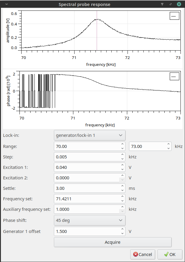
After the frequency range is selected, the spectrum can be acquired and, by mouse, the operating frequency (also seen in “Frequency set” control) can be chosen. Note that only generator/lockin1 is relevant for tapping mode operation settings. Parameters “Excitation 2” and “Auxiliary frequency set” have no connection to it.
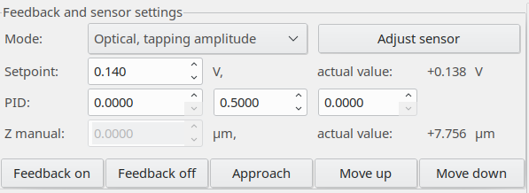
When the frequency and amplitude are chosen, user needs to select the setpoint value. In case of amplitude based feedback it is always value lower than the actual one, in case of phase based feedback it should be also the case mostly. The same controls like in the case of contact mode can be used to control the feedback loop. An example of feedback parameters when tapping mode is in operation are shown here: